Obsah
XMOS startKIT
Board contains mysterious microcontroller from XMOS. This board is not available in our lab, however few of us have it. In case you want to experiment with this board, you can try to ask us.
If you have discovered anything useful about programming tile[0] (or any other undocumented feature of startKIT) just add it to this page or contact Fosfor. (Also any English corrections are welcomed ![]() )
)
Features
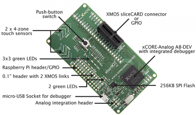
- mysterious 8A6C5DEV XMOS microcontroller (said to be „xCORE-Analog 8-core device with integrated debugger“)
- micro-USB connection to host debugger
- PCIe connector for sliceCARD add-on boards
- 0.1„ header compatible with Raspberry PI
- Two 4-zone cap sense sliders
- 3×3 LED matrix
- 2 additional LEDs
- Push-button switch
- 4 ADC inputs
- 256KB SPI Flash
- 0.1“ header for connecting additional startKITs
What has been discovered
- Microcontroller seems to be XS1-U16A-128-FB217 (datasheet) - with two tiles, 16 cores.
- Flash memory is connected to the tile[1] and is empty at the beginning.
- Tile[0] has some sort of bootloader burned into its OTP. This bootloader is able to load tile[1] from flash (if there is something to load) or load into tile[1] default demo (glowing LEDs). Moreover it presents itself on the USB as „XMOS startKIT“ device (PID 0xf7d3) with similar bootloader the xTAG-2 external debugger contains.
- By slightly modified run_dynamic_xe application from proj_xtag2 user code can be run on tile[0] (so USB part and all 16 cores can be used by user application) - see below. XMOS Application Note: Dynamic loading of USB Binaries onto the XTAG2 can be useful.
- Board-edge connector TP1 can be connected to the external xTAG-2 debugger. (So far both two tiles can be communicated with, but we are unable to run code by this way.)
How to programme tile[0]
Basically there are (should be) two ways of uploading your own code into tile[0] - by the bootloader burned into OTP of tile[0] or by the JTAG connected to TP1 board-edge connector. The first one is working for us, the second don't.
Running code using bootloader
- Compile some code to run on tile[0]. Use definition for XS1-U16A-128-FB217 but use only one tile. You can use USB PHY, which is on this tile. You should get *.xe file from this step.
- Extract binary from your XE file. This should be done by tool
xobjdumpwith option-s –strip. (My binary to use is named image_n0c0_2.bin.) - Get run_dynamic_xe and change
XMOS_XTAG2_PIDfrom 0xf7d1 (for XTAG2) to 0xf7d3 (for StartKIT). You will also need this USB binaries. - Force
run_dynamic_xeto read your binary instead ofint burnData[]from header file. This can be achieved by converting your bin file into array of ints or (better) by learningrun_dynamic_xeto read it from file. - Load your binary into tile[0]
- Disconnect startKIT (if connected).
- Connect startKIT with micro-USB cable to your PC.
- Run
run_dynamic_xe. DO NOT run any other XMOS tool before loading your binary.
- Now it should be running your code.
run_dynamic_xeautomatically soft-reset USB after your binary is loaded, so you do not need to unplug it from your PC. When you unplug USB cable from PC, startKIT will loose its power and it will forget your code. On next reconnect the bootloader will be again active presenting itself as „XMOS startKIT“. So it seems to be unbreakable
Running code using xTAG-2
- Connect your xTAG-2 to the TP1 connector of your startKIT. Pins are shown in a table below.
- Disconnect micro-USB if connected and connect xTAG-2 to your PC.
- Use the startKIT with xTAG-2 as any other board. You should create your XN file derived from
STARTKIT.xnandXS1-U16A-128-FB217-C10.xn.
(This should work, but it doesn't. We are able to identify two L tiles on the JTAG, we are able to query its actual PC/stack/registers state, but we are unable to run any application by this method.)
| xTAG-2 XSYS | startKIT TP1 | ||
|---|---|---|---|
| pin | description | pin | description |
| 1 | 5V power | 5 | 5V power |
| 3 | JTAG Test Reset - Active Low | M | MSEL (MODE[2], MODE[3]) |
| 5 | JTAG Test Data (to target) | I | TDI |
| 7 | JTAG Test Mode Select | S | TMS |
| 9 | JTAG Test Clock | K | TCK |
| 11 | Debug | D | DEBUG_N |
| 13 | JTAG Test Data (from target) | O | TDO |
| 15 | System Reset - Active Low. | R | RST_N |
| 20 | Ground | G | Ground |


